

Easy 3 Way Switch Wiring Diagram for Every Homeowner
Have you ever flipped a light switch at the bottom of the stairs, only to turn it off again from the top? That’s the magic of a three-way switch. Understanding a 3 way switch wiring diagram is the key to making this work safely and correctly.
Whether you’re a curious homeowner or a beginner DIYer, this guide breaks it all down in plain language. You’ll learn how the circuit works, how to read the diagram, and how to wire it up step by step — no electrician degree required.
What Is a 3 Way Switch Wiring Diagram?
A 3 way switch wiring diagram is a visual map of how two switches connect to control one light from two different locations. It shows the path electricity travels from the power source, through both switches, and on to the light fixture.
Unlike a standard single-pole switch (which has just two terminals), a three-way switch has three terminals:
- Common terminal (usually black or darker screw)
- Traveler terminal 1
- Traveler terminal 2
The diagram makes it easy to see which wire goes where. Without it, you’re just guessing — and guessing with electricity is never a smart idea.
Why You Need a Wiring Diagram
A 3 way switch wiring diagram removes the guesswork. It shows wire colors, terminal connections, and the direction of current flow. This is especially helpful because three-way switch wiring can vary based on where the power enters the circuit — at the switch box or at the light fixture.
How Does a 3 Way Switch Circuit Work?

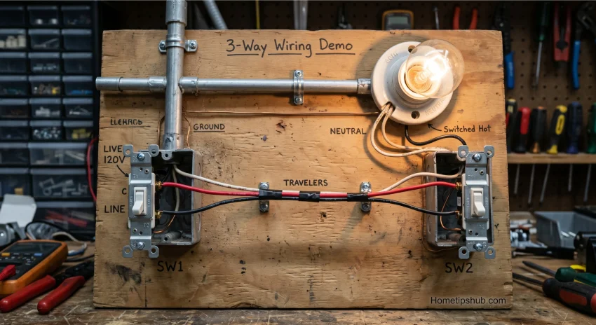
Let’s make this simple. Think of a three-way circuit like a railroad track with two switches that redirect the train. When both switches point the same way, power flows and the light turns on. When they point in opposite directions, the circuit breaks and the light turns off.
Here’s the basic flow:
- Power enters the first switch box
- Traveler wires carry current between the two switches
- The common wire delivers power to the light when the circuit is complete
Understanding the Traveler Wires
The traveler wires are the two wires that run between your switches. They’re the backbone of any 3 way switch wiring diagram. These wires alternate which one carries live current depending on the switch position.
Most electricians use 14/3 cable (with red, black, and white wires) for the traveler run. The red and black wires serve as travelers, while the white wire is used as the neutral or sometimes repurposed as a traveler (and should be marked with tape).
Types of 3 Way Switch Wiring Configurations
Not all 3 way switch wiring diagrams look the same. The layout depends on where the power enters the circuit. Here are the three most common setups:
Power at the First Switch Box
This is the most common configuration. Power comes into switch box #1, travels through the two switches via traveler wires, and exits to the light fixture through the common terminal of switch #2.
Power at the Light Fixture
In this setup, power enters at the light fixture first, then runs back to both switch boxes. The neutral wire stays at the fixture, and switched power travels through the circuit.
Power in the Middle (Switch Loop)
This is the trickiest layout. Power enters somewhere between the two switches. The 3 way switch wiring diagram for this setup is more complex, but the same terminal rules apply.
Step-by-Step: How to Wire a 3 Way Switch
Now let’s get practical. Here’s a clear, proven process to wire your 3 way switch safely.
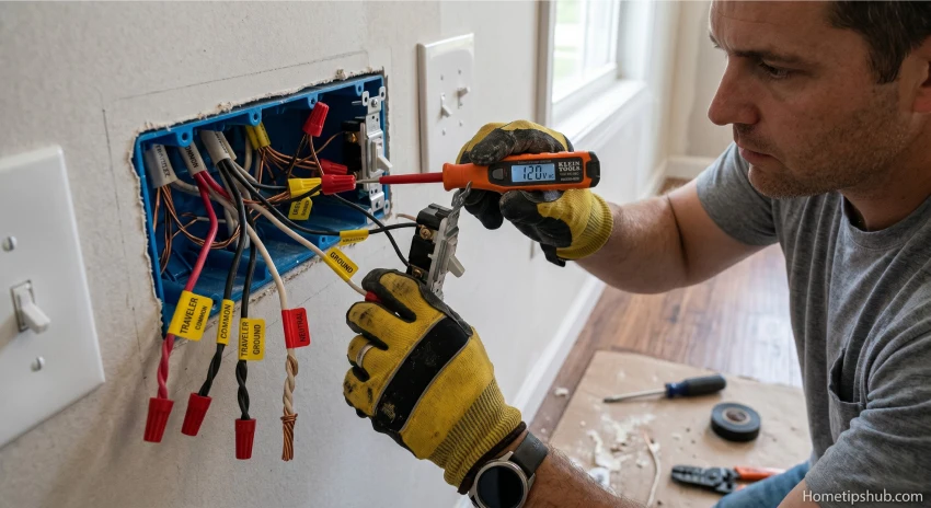
Before you start: Turn off the breaker. Use a voltage tester to confirm the power is off. Never skip this step.
Step 1 — Identify Your Wires
Pull out the wires from the switch box and identify:
- Black wire — typically the hot/common wire
- White wire — neutral (or traveler if marked)
- Red wire — traveler wire
- Bare copper or green wire — ground
Step 2 — Connect the Common Terminal
The common terminal (dark screw) always gets the wire bringing power in (at switch #1) or sending power to the light (at switch #2). This is the most critical connection in the 3 way switch wiring diagram.
Step 3 — Connect the Traveler Wires
Attach the traveler wires (red and black) to the two lighter-colored screws on each switch. It doesn’t matter which traveler goes to which traveler terminal — as long as both switches use the same wire on the same terminal.
Step 4 — Connect the Ground Wire
Attach the bare copper ground wire to the green screw on the switch. This is a safety step that protects against electrical faults.
Step 5 — Test the Circuit
Restore power at the breaker. Flip switch #1 — the light should turn on or off. Then flip switch #2 — it should do the opposite. If both switches control the light independently, your 3 way switch wiring is correct.
3 Way Switch Wiring Diagram: Quick Reference Table
| Component | Location | Wire Color | Purpose |
|---|---|---|---|
| Common Terminal | Switch #1 | Black | Receives power from source |
| Traveler Wire 1 | Between switches | Red | Carries alternating current |
| Traveler Wire 2 | Between switches | Black | Carries alternating current |
| Common Terminal | Switch #2 | Black | Sends power to light |
| Neutral Wire | Light fixture | White | Completes the circuit |
| Ground Wire | Both switches | Bare copper/Green | Safety grounding |
Common Mistakes When Reading a 3 Way Switch Wiring Diagram
Even careful DIYers make mistakes. Here are the most common ones — and how to avoid them.
Mixing Up the Common and Traveler Terminals
The common terminal is the dark-colored screw. The traveler terminals are the lighter ones. Mixing these up is the #1 mistake people make when following a 3 way switch wiring diagram. Always double-check before connecting.
Using the Wrong Cable Type
Standard 14/2 cable (black, white, ground) only works for single-pole switches. For three-way switch wiring, you need 14/3 cable (black, white, red, ground) for the run between the two switches.
Ignoring Wire Markings
If a white wire is used as a traveler or hot wire, it must be marked with black or red electrical tape. This is required by the National Electrical Code (NEC) and helps anyone who works on the circuit later understand the wiring configuration.
Smart Tips for Reading Any 3 Way Switch Wiring Diagram
Reading a 3 way switch wiring diagram gets easier with practice. Here are some smart tips to speed things up:
- Start at the power source and trace the path to the light
- Identify the common terminals first — they anchor the whole diagram
- Color-code your wires with tape before disconnecting anything
- Take a photo of the existing wiring before you remove any wires
- Use a continuity tester to verify your connections before turning on the breaker
- Label your cables at both ends when running new wire through walls
These habits make it much easier to follow even a complex three-way wiring diagram without getting confused.
When to Call a Licensed Electrician
Most 3 way switch wiring projects are DIY-friendly, but there are times when it’s smarter to call a pro:
- You find aluminum wiring (common in older homes built before 1972)
- The junction box is overcrowded with too many wires
- You’re not sure which wire is the common terminal wire
- The circuit keeps tripping the breaker after wiring
- You’re working in a wet location like a bathroom or outdoor area
Safety always comes first. A licensed electrician can also pull permits if your local code requires it for electrical wiring changes.
FAQ: 3 Way Switch Wiring Diagram
Q1: What is the most important wire in a 3 way switch wiring diagram?
The common terminal wire is the most critical. At switch #1, it brings power into the circuit. At switch #2, it sends power to the light. Getting this wire right is the foundation of any correct 3 way switch wiring diagram. Always connect it to the dark-colored screw on the switch.
Q2: Can I use a regular switch instead of a 3 way switch?
No. A standard single-pole switch only has two terminals and cannot function as part of a three-way circuit. You need switches specifically labeled as 3 way switches, which have three terminals and no ON/OFF markings on the toggle.
Q3: Why does my light stay on even when I flip both switches?
This usually means the traveler wires are crossed or connected to the wrong terminals. Recheck your 3 way switch wiring diagram and confirm the travelers are connected to the lighter-colored screws and the common wire is on the dark screw.
Q4: How many wires should I see in a 3 way switch box?
In a typical 3 way switch wiring setup, you’ll see at least four wires at each switch box: a black (common), red (traveler), white (neutral or traveler), and a bare copper ground. Some boxes may have more wires if circuits pass through them.
Q5: Is a 3 way switch wiring diagram the same for smart switches?
Not exactly. Smart switches for three-way circuits often require a neutral wire at both switch boxes, which older wiring setups may not have. Some smart switches use a remote module instead of a true second switch. Always check the manufacturer’s wiring diagram before installing.
Conclusion
A 3 way switch wiring diagram might look complicated at first glance, but once you understand the role of the common terminal, the traveler wires, and the neutral wire, it all makes perfect sense. The circuit is elegant — two switches sharing a conversation through a pair of wires, deciding together whether the light should be on or off.
Start by identifying your wiring configuration, follow the diagram carefully, and always test with the breaker off. Whether you’re wiring a staircase, hallway, or large room, this guide gives you everything you need to do it right.
Go ahead — grab your wire stripper and make it happen. You’ve got this.