


Have you ever wanted to turn a light on at the bottom of the stairs and off at the top? That’s exactly what a 3 way switch setup does, and understanding the electrical diagram 3 way switch layout makes the job simple.
This wiring method lets you control one light fixture from two different switches. It’s common in hallways, staircases, and large rooms with multiple entry points.
Many homeowners feel nervous about electrical wiring, but once you see the electrical diagram 3 way switch, the logic becomes clear. This guide breaks it down step by step.
We’ll cover terminals, traveler wires, common wiring mistakes, and safety tips. By the end, you’ll be able to read any electrical diagram 3 way switch with confidence.
What Is an Electrical Diagram 3 Way Switch?
An electrical diagram 3 way switch is a visual map showing how two switches work together to control a single light. Unlike a regular single pole switch, this setup uses three terminals instead of two.
The extra terminals allow current to travel through two different paths, known as traveler wires. These wires connect the two switches so either one can turn the light on or off.
Why Homes Use This Wiring
This wiring style is popular because it adds convenience. You don’t have to walk back across a room just to flip a switch.
Common places you’ll find an electrical diagram 3 way switch include:
- Stairways with switches on each floor
- Long hallways with entry points on both ends
- Garages with doors leading to different areas
- Bedrooms with switches near the door and the bed
Basic Components
Every electrical diagram 3 way switch includes a few key parts. These are the common terminal, two traveler terminals, and the ground connection.
Understanding these parts is the first step toward wiring the circuit correctly and safely. We’ll dig deeper into each part in the next section.
How Does the Common Terminal Work?
The common terminal is the heart of any electrical diagram 3 way switch. It’s usually a darker colored screw, often black or copper, compared to the lighter traveler screws.
On one switch, the common terminal connects to the power source. On the other switch, it connects to the light fixture itself.
Identifying the Common Screw
If you’re not sure which terminal is common, check the switch body. Most switches have the common terminal marked or colored differently from the two traveler terminals.
This distinction matters a lot. Wiring the common terminal incorrectly is one of the most frequent mistakes people make when following an electrical diagram 3 way switch.
Testing for Accuracy
Before finalizing your work, always test with a voltage tester. Turn off the breaker first, then verify there’s no live current before touching any wires.
Once confirmed safe, you can trace the common wire back to its source. This simple habit prevents shocks and wiring errors, keeping your project both efficient and secure.
What Are Traveler Wires and Why Do They Matter?
Traveler wires are the two wires that run between the pair of switches in an electrical diagram 3 way switch. They carry the switching signal back and forth.
Think of travelers like train tracks. The current can travel down either path depending on the switch position, which is what allows both switches to control the same light.
How Traveler Wires Connect
Each switch has two traveler terminals, usually brass colored. These connect directly to the matching traveler terminals on the other switch.
A key rule: never connect traveler wires to the common terminal. Doing so will cause the circuit to malfunction or short out.
Common Wire Colors
While not universal, many electricians follow a color pattern:
| Wire Color | Typical Function |
|---|---|
| Black | Common or hot wire |
| Red | Traveler wire |
| White | Neutral wire |
| Green/Bare | Ground wire |
Following this pattern makes any electrical diagram 3 way switch easier to read and troubleshoot later, especially if another person works on the circuit down the road.
Step-by-Step Wiring Instructions

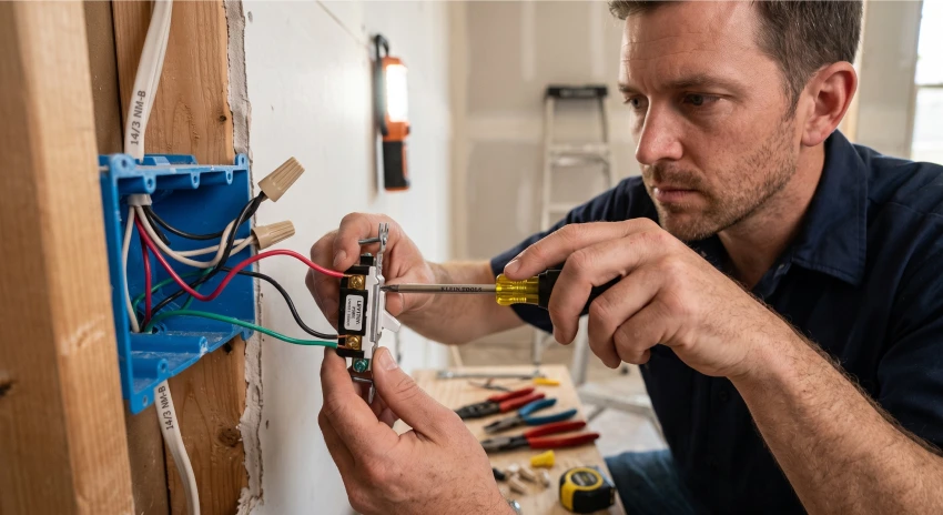
Now let’s walk through wiring an electrical diagram 3 way switch from start to finish. Take your time with each step for the best results.
Step 1: Turn Off Power
Always shut off the breaker before starting. Safety comes first, no exceptions, when working with any home wiring project.
Step 2: Identify Wires
Locate the common, traveler, and ground wires at both switch boxes. Label them if needed to avoid confusion later.
Step 3: Connect the Common Terminals
Attach the common wire from the power source to the common terminal on the first switch. Then connect the common wire from the light fixture to the second switch.
Step 4: Connect Traveler Wires
Run the two traveler wires between both switches, connecting matching terminals. This completes the switching loop.
Step 5: Attach Ground Wires
Connect all ground wires to the green screw on each switch and to the metal box if applicable.
Step 6: Test the Circuit
Restore power and test both switches. The light should turn on and off from either location smoothly.
Following this electrical diagram 3 way switch sequence carefully reduces errors and keeps your household wiring safe and reliable for years to come.
Common Mistakes to Avoid
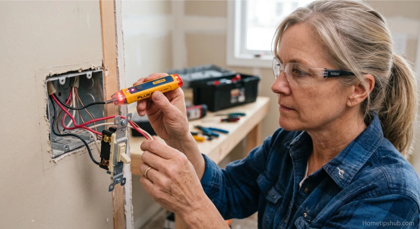
Even simple projects can go wrong without the right knowledge. Here are frequent errors people make with an electrical diagram 3 way switch.
Mixing Up Terminals
Confusing the common terminal with a traveler terminal is the top mistake. This causes the switches to work backward or not at all.
Skipping the Ground Wire
Some people forget the ground connection entirely. This creates a serious safety hazard and violates most NEC wiring code standards.
Using the Wrong Switch Type
A standard single pole switch cannot replace a 3 way switch. They look similar but function very differently inside.
Poor Wire Nut Connections
Loose wire nut connections can cause flickering lights or complete circuit failure. Always twist wires firmly and tug-test each connection.
Avoiding these mistakes when reading your electrical diagram 3 way switch will save you time, money, and potential frustration down the line.
Time-Saving Comparison Table
Below is a quick comparison to help you decide which wiring approach fits your project best.
| Method | Time Needed | Difficulty | Best For |
|---|---|---|---|
| Basic single pole switch | 15 minutes | Easy | One switch, one light |
| Electrical diagram 3 way switch | 45 minutes | Moderate | Two switches, one light |
| Four way switch diagram | 90 minutes | Advanced | Three or more switches |
| Smart dimmer switch wiring | 60 minutes | Moderate | Adjustable lighting |
As you can see, the electrical diagram 3 way switch sits right in the middle. It’s more involved than basic wiring but still very manageable for a confident DIYer.
When Should You Call a Professional Electrician?
Not every project is a DIY job. Knowing your limits keeps your home and family safe.
Signs You Need Help
If your electrical panel looks outdated, or you’re unsure about circuit breaker wiring, it’s best to call a licensed electrician.
Also, if local codes require permits for wiring changes, a professional can ensure everything meets NEC wiring code requirements.
Benefits of Hiring an Expert
A trained electrician can quickly read any electrical diagram 3 way switch and spot issues you might miss. They also carry insurance in case something goes wrong.
While hiring help costs more upfront, it often saves money by preventing future repairs or fire hazards caused by faulty home electrical safety practices.
DIY vs Professional Checklist
- DIY: Simple swaps, basic switch replacement, single circuits
- Professional: Panel upgrades, new circuit installs, complex multi-switch setups
Balancing confidence with caution ensures your electrical diagram 3 way switch project turns out safe and long-lasting, whether you handle it yourself or bring in expert help.
Frequently Asked Questions
1. What is the main purpose of an electrical diagram 3 way switch?
The main purpose is controlling a single light fixture from two separate locations. This is useful in staircases, hallways, and rooms with multiple doorways, offering convenience and improved energy efficiency for daily lighting needs.
2. Can I use a regular switch instead of a 3 way switch?
No, a standard single pole switch only has two terminals and cannot handle the traveler wire connections required. You must use a switch specifically designed for 3 way switch wiring configurations.
3. How many wires are needed for an electrical diagram 3 way switch?
Typically, you need four wires: one common wire, two traveler wires, and one ground wire. Some setups may also include a neutral wire depending on your local NEC wiring code requirements.
4. Is wiring an electrical diagram 3 way switch dangerous?
It can be risky if power isn’t turned off first. Always test wires with a voltage tester before touching them, and follow proper home electrical safety steps throughout the entire project.
5. What’s the difference between a 3 way and 4 way switch?
A 3 way switch controls a light from two locations, while a four way switch diagram adds a third control point. Four way switches sit between two 3 way switches in the circuit.
Conclusion
Understanding an electrical diagram 3 way switch doesn’t have to feel overwhelming. Once you know the common terminal, traveler wires, and proper sequence, the whole process becomes much clearer.
We covered the basics, step-by-step instructions, common mistakes, and when to call a professional. Each section builds toward one goal: helping you wire confidently and safely.
Remember to always turn off power first and test your work before finishing up. Safety should never take a back seat to speed.
Whether you’re tackling a hallway light or a staircase fixture, this electrical diagram 3 way switch guide gives you the tools to succeed. Ready to get started? Grab your tools, double-check your wiring diagram, and take on your next lighting project with confidence.